- Phone Actuator (RG Module) Required
- Maid Phone (RK Module) Required
- Voicemail (RG Module) Required
Overview
The RDP Phone Actuator interface turns the phone on for outside calls in the guest room once the guest checks-in. It then turns the phone off to outside calls when the guest checks-out. With certain phone switches, Phone Actuator also displays the guest name on the phone system when the guest places a call to the front desk.
The Maid Phone interface allows the housekeeper to dial a specific code indicating that cleaning is in progress and dials a different code once the room is clean. This updates the status of the room in RDP automatically.
The Voicemail interface turns on the voicemail when the guest checks-in and turns it off when they check-out.
Typically, all three modules are integrated into the phone switch.
| Communications Diagram |
|---|
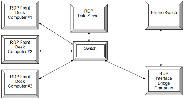
|
Hardware
The workstation running the Phone Actuator Interface must be a 32-bit workstation with at least one serial port. Pervasive must be installed because the RDP DOS program will run the phone interface. The RDP interface computer connects with the phone switch using a null modem cable. Generally, the Phone Actuator and Maid Phone communicate using the same serial port, while Voicemail is a separate port from the phone switch. For more information, contact RDP Support.
Technical Information
- RDP communicates using HOBIC protocol.
- RDP communicates with the phone switch using a RS-232 serial cable.
- A null modem cable connects the RDP interface computer to the phone switch. A 9-pin or 25-pin cable can be used.
- If using a 9-pin cable, RDP sends the message on pin #2 and receives on pin #3. Pin #5 is the ground or 'straight through' pin.
- If using a 25-pin cable, RDP sends the message on pin #2 and receives on pin #3. Pin #7 is the ground or 'straight through' pin.
RDP Configuration
- Run the appropriate UPD based on the phone switch.
- In RDP DOS, go to the 98-System Manager Functions --> 094-Update File Paths.
- In field 17, enter RG for Phone Actuator, RK for Maid Phone, and RM for Voicemail. The module code is required in order to access the RDP Phone programs.
- Configure the CR Table with the extension to room number and the RE with the room to extension. In RDPWin, go to the System main menu --> Table Maintenance --> select Table CR or RE from the drop down. In RDP DOS --> go to the 98-System Manager Functions --> 090-Update System Tables --> U-Update Table Records --> enter CR to access the CR table or RE to access the RE table.
- Set the communication parameters for the phone interface. In RDP DOS, go to menu 17-Call Accounting Interface --> CFG-Interface Setup Options --> 3-RG: Phone Actuator Parameters --> 2-Communication Parameters. Confirm the settings with the technician or vendor.
- Set the communication parameters for the maid interface. In RDP DOS, go to menu 17-Call Accounting Interface --> CFG-Interface Setup Options --> 5-RK: Maid Interface Parameters --> 2-Communication Parameters. Confirm the settings with the technician or vendor.
- Set the communication parameters for the voicemail interface. In RDP DOS, go to menu 17-Call Accounting Interface --> CFG-Interface Setup Options --> 6-RM: Voicemail Parameters --> 2-Communication Parameters. Confirm the settings with the technician or vendor.
Testing
- Go to the Phone Actuator program in RDP DOS, from menu 17-Call Accounting Interface --> 736-Telephone Interface Program --> 1-Process Messages.
- Turn on the debug by hitting the Alt+D keys.
- Check-in a test reservation into a guest room. Verify that the phone in the room has been turned on for outside calls.
- View the debug by pressing the ALT+V keys.
- Make any necessary adjustments to the communication parameters.
Troubleshooting
To troubleshoot the phone actuator interface that is already installed:
- Determine if communication exists between the RDP phone actuator interface and the phone switch.
- Turn on debug and check-in a test reservation.
- If no activity occurs on the interface program screen after the reservation is checked in, there is likely no communication between RDP and phone switch. No communication indicates there is some type of hardware failure, such as a bad serial port or cable.
- Check the serial cable are connected to both computers.
- Test the serial ports and cables.
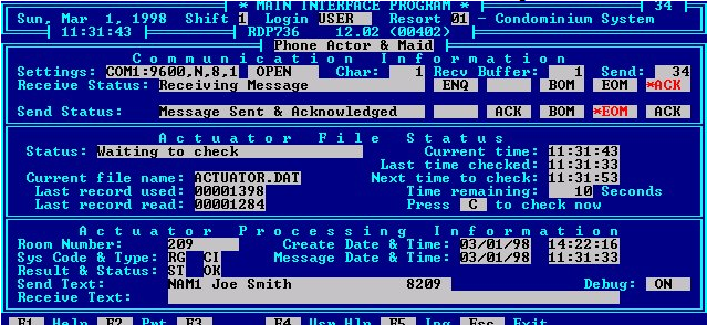
RDP736 Successful Phone Actuator Message
Glossary
Here a list of commonly used terms:
- Serial Communication: A stream of data being sent between two systems via a RS-232 serial cable and two communication ports. The transmission of data as a sequence of bits.
- Serial or Communication Ports: An I/O (Input/Output) port that communicates with external devices. A serial port, also called a "bit" device, sends an receives data one bit at a time over one wire. Two-way (full duplex) communications is possible with one three separate wires - one to send, one to receive, and a common or ground wire. This device is commonly called a 'com' port in RDP.
- RS-232C Serial Cable: A cable attached to a communications port through which the data stream travels between two computers. RS stands for "Recommended Standard."
- Null Modem Cable: A null modem cable reverses the sense of the transmit and receive lines.
- HOBIC Data Protocol: A series of characters used as a common protocol in serial communication between a PMS (Property Management System) and POS system. RDP supports HOBIC protocol.
- HOLIDEX Data Protocol: A series of characters used as a common protocol in serial communication between a PMS (Property Management System) and a POS system. RDP support HOLIDEX protocol.
- Pin Out: Pins being used to communicate or transfer data across a serial cable.
- Data Bits: The serial communication standards allow for the transmission of different lengths of characters. When communication software asks for the length, it is asking whether the sending device is using seven or eight bit characters.
- Stop Bits: At the end of each frame, stop bits are send. There can be one, one and a half, or two stop bits. The stop bits force a certain minimum gap between frames. There are always at least one stop bit.
- Parity: A method of testing whether the transmission is being received correctly. The sending device adds a parity bit which calculated according to the contents of the data bits.
- Even Parity: The total of the data bits and the parity bit equal an even number.
- No Parity: A parity bit is not always used. It may be ignored by the received device if it used. No parity means there is no parity bit being sent.
- Odd Parity: The total of data bits plus the parity bits equal an odd number.
- Handshaking: Handshaking signals are sent as data along the data wires instead of along the dedicated handshaking circuits. There are several standard protocols of software handshaking including: ENQ/ACK, ACK/NAK, and XON/XOFF.
- BOM/EOM Characters: The BOM (beginning of message) and the EOM (end of message) characters are characters that frame the call record so RDP knows where each record begins and ends. Standard BOM character is 02 (STX) and the EOM is 03 (ETX).
- Extra Characters: Some systems send additional characters after teh EOM character. RDP has to know to ignore these by counting them as extra characters.
- ACK Character: A character used to acknowledge the receipt of a message. Standard ACK character is a 06 (ACK).
- NAK Characters: A character send as a negative acknowledgement in receipt of a message. Standard NAK character is 21 (NAK).
- Hexadecimal Character: Common character type used in HOBIC communication.
- Data Swap: Also called a Keep Alive Message, a stream a data to confirm communication between systems. RDP does NOT support data swap.
- Debug: A log within RDP that records the data stream being send between the two systems.